Sub-6GHz Antenna Testing Application Experiment
System Principle
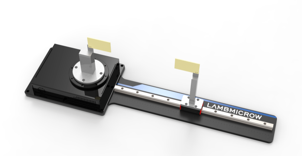
The Sub-6GHz antenna testing application experiment is constructed with a host computer, the primary experimental equipment vector network analyzer (VNA), and the RF microwave teaching and research platform kit. The kit includes antenna testing fixtures, antenna testing jigs, teaching experimental antennas, cable assemblies, installation tools, etc.
Experimental Procedure
A teaching experimental antenna is mounted as the transmitting antenna on the antenna testing fixture. The excitation signal from port 1 of the vector network analyzer is delivered to the transmitting antenna via an RF cable for emission. At the receiving end, another teaching experimental antenna is mounted on a slider. Under the control of the host computer, the receiving antenna rotates with the turntable on the antenna testing fixture within a set azimuth range and at a specified rotational speed. The received signal is fed into port 2 of the vector network analyzer for processing. At regular angular intervals, the small receiving turntable sends a trigger pulse to the vector network analyzer. Upon receiving the pulse signal, the vector network analyzer performs a data acquisition from the receiving antenna. The host computer retrieves raw test data from the vector network analyzer via LAN bus, while simultaneously controlling the antenna turntable via serial bus. By rotating the antenna turntable, measurement data from all directions of the antenna under test (AUT) are collected. Subsequent processing calculates the antenna’s radiation pattern parameters and plots the radiation pattern curve, completing the radiation pattern experiment. Based on this, parameters such as antenna gain and polarization characteristics are derived, finalizing the antenna gain and polarization characteristics experiments.
This testing application experiment enables students to experience and learn:
· Teaching of antenna principles and testing systems
· Use of vector network analyzers
· Antenna standing wave ratio (SWR) testing experiments
· Radiation pattern testing and interpretation of gain data
On the fixed configuration, experimental modes can be iterated through self-developed, self-purchased, or optional experimental components:
· Provides aperture dimensions for printed circuit boards of printed antennas, facilitating course design
· Provides mounting hole dimensions for antenna installation parts, enabling users to design and fabricate adapters for self-developed or purchased miniaturized antennas, supporting application expansion
· Offers functional upgrade options for the RF microwave teaching and research platform kit, extending applications to additional frequency bands and diverse experiments
Main Indicators and Experimental Configuration
1.System Indicators
Operating frequency range:1GHz~6GHz
2.Turntable Indicators
Payload: ≥ 0.5 kg
Rotation range: -180°~180°
Rotation speed: 3°/s
3.Antenna Indicators
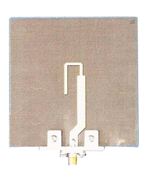
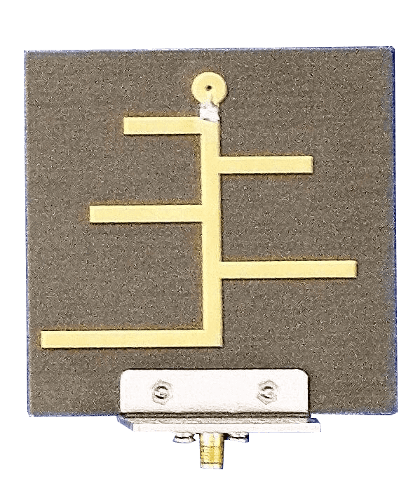
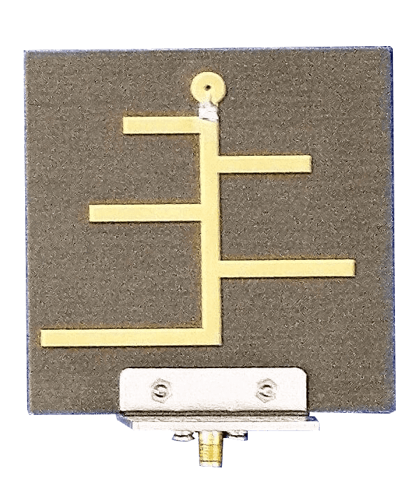
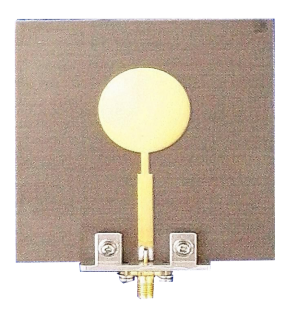
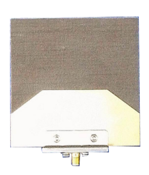
Printed Vivaldi Antenna: Frequency range 6 GHz
Printed Yagi Antenna: Frequency range 2 GHz
Printed Log-periodic Antenna: Frequency range 5 GHz
Printed Monopole Antenna: Frequency range 3 GHz
4.Power Supply
AC voltage: 220V±10%
Frequency: 50Hz±10%
Power: ≤400W
Introduction to Experimental Equipment for Sub-6GHz Antenna Testing Applications
|
Description |
Sample |
|
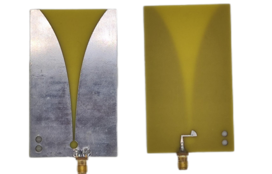
Printed Vivaldi Antenna |
|
|
Printed Yagi Antenna |
|
|
Printed Log-periodic Antenna |
|
|
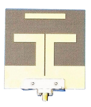
Printed Monopole Antenna |
|
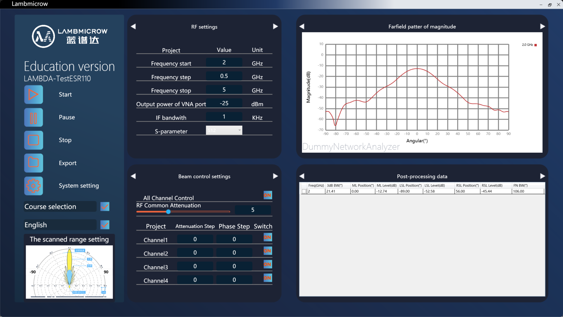
Software System
Independent channel angle settings: Allow angle configuration for each channel during a single scan.
User-driven software: The 2D far-field measurement software simplifies parameter input and enables direct result viewing within the same interface.
Software customization: Supports versatile interface customization and modification.